¶ Technical specification
| Compatibility | P1 companion interface |
| Power meter interface | RJ12 |
| Connection | Wi-Fi 2.4GHz b/g/n |
| Power | Powered from the meter |
| Weight (incl enclosure) | 40 g |
| Size | 70 x 39 x 24 mm |
| Input voltage | 5V |
| Operating power | 0,4 W |
| Data encryption | Supported |
| MQTT | Internal and external, including SSL |
| Home Assistant auto discovery | Yes |
| Protection class | IP20 (suitable for use in dry conditions) |
| Temperature range | -20°C to +70°C |
| Humidity | Non-condensing |
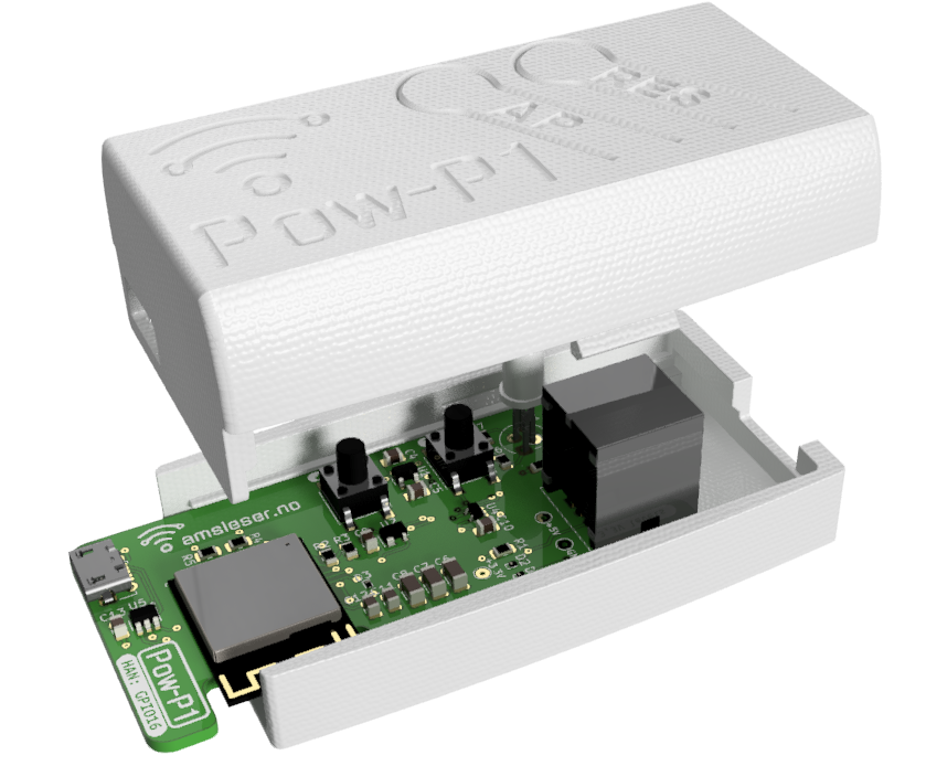
¶ Overview
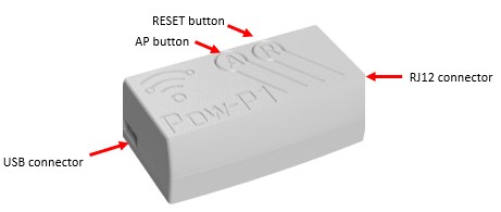
¶ Buttons
There are two buttons:
- Pressing the RES / R button restarts the microcontroller. Restart is indicated by a blink sequence on the LED.
- Holding the AP / A button down for 5-10 seconds sets the device in Access point (AP) mode. Do this if you need to reconfigure the Wi-Fi setting.
AP mode is indicated by steady yellow light on the LED (on older firmware: short yellow blinks).
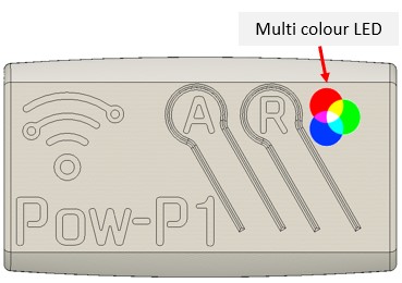
¶ Indicator LEDs
The multicolour LED gives the following indications:
- Steady yellow light when device is in Access point (AP) mode
- Rapid green/red/yellow blink sequence when restarting
- Blue blinking while data arrives from the power meter
- Short green blink immediately after blue blinking: Data is recognized as valid.
- Red blink codes indicates errors. See Firmware User Manual.
- Steady blue light when the device is powered but not connected to the power meter.
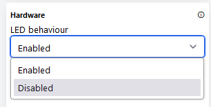
If the blinking from the LED is disturbing during use, it can on newer hardware be deactivated in the settings:
¶ Getting started
Follow the Getting started guide to connect the device to Wi-Fi and complete initial configuration.
¶ Optional (user installable) temperature sensor
Pow-P1 boards can accommodate a user-installed temperature sensor, type TMP36GRT (U6 on the board). This is an analog temperature sensor.
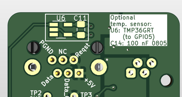
User should also install a 100 nF decoupling capacitor in the allocated position (C11).
To activate the temperature sensor, user must change the hardware setting:
- Add "/vendor" to the URL and select "Generic ESP32-S2" and "GPIO16" from the dropdown lists:
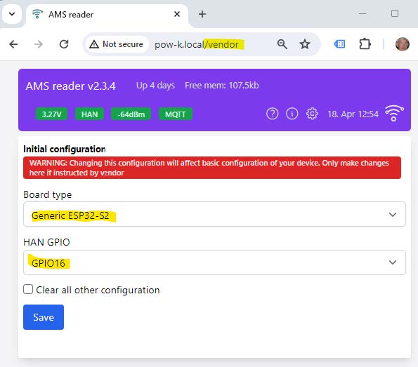
- Click "Save"
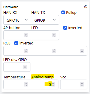
- Open the Config page
- You will now see a modified "Hardware" tile, with a field named "Analog temp", which must be set to "5" (corresponding to "GPIO5" marked on the PCB):
- In the "User interface" tile, ensure that "Temperature plot" is set to "Auto" or "Enabled":
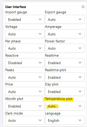
- Click the blue "Save" button (bottom right) to save the changes.