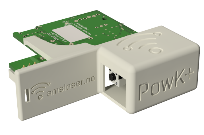
 Pow-K |
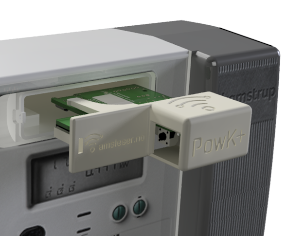 Pow-K and Kamstrup Omnipower meter |
¶ Technical specification
| Compatibility | - Kamstrup Omnipower meters configured for “Data push” - Kamstrup Omnipower meters configured as “P1 port” (requires firmware v2.3.5 or newer and board version v1.6.1 or newer) - Kamstrup 382M meters that cannot be configured for “Data push”. This feature only works on Pow-K boards layout v1.6.x and newer. |
| Power meter interface | Plugs into the expansion bay of Kamstrup power meters |
| Connection | Wi-Fi 2,4 GHz b/g/n |
| Power | Powered from the meter |
| Data refresh rate | The Kamstrup Omnipower sends data each 10 second |
| Weight | 40 grams |
| Size | 73,5 x 70 x 22 mm (including 3D printed holder) |
| Voltage | - 4,15 V when plugged into the Kamstrup meter - 5V when powered from the USB connector (not plugged into the meter) |
| Operating power consumption | 70 mA |
| Maximum power consumption (during firmware upgrade): |
135 mA |
| Data encryption | Supported |
| MQTT | Internal and external, including SSL |
| Home Assistant auto discovery | Yes |
| Protection class | Protection class: IP20 (suitable for use in dry conditions) |
| Temperature range | -20°C to +70°C |
| Humidity | Non-condensing |
¶ Overview
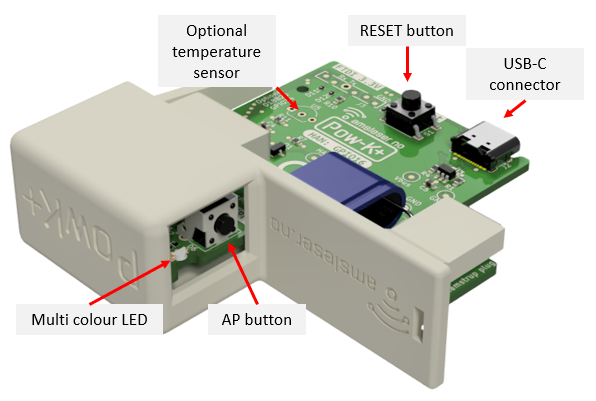
Device overview
¶ Buttons
There are two buttons:
- Pressing the RES / R button restarts the microcontroller. Restart is indicated by a blink sequence on the LED.
- Holding the AP / A button down for 5-10 seconds sets the device in Access point (AP) mode. Do this if you need to reconfigure the Wi-Fi setting.
Important: When in AP mode, the Pow-U must be powered from USB, as this mode consumes more current than the power meter can deliver.
AP mode is indicated by steady yellow light on the LED (on older firmware: short yellow blinks).
¶ Indicator LED
The multicolour LED gives the following indications:
- Steady yellow light when device is in Access point (AP) mode
- Rapid green/red/yellow blink sequence when restarting
- Blue blinking while data arrives from the power meter
- Short green blink immediately after blue blinking: Data is recognized as valid.
- Red blink codes indicates errors. See Firmware User Manual.
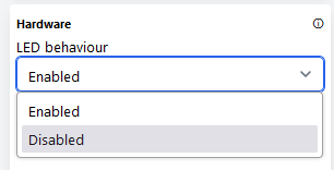
If the blinking from the LED is disturbing during use, it can on newer hardware (Pow-K layout 1.6.x and newer) be deactivated in the settings:

Installing the Pow-K board in a Kamstrup HAN-NVE module
The board can be installed to replace the original card of a Kamstrup HAN-NVE module.
This is a good solution for users in Norway that receive the HAN-NVE module from the grid company, or have it pre-installed on the meter:
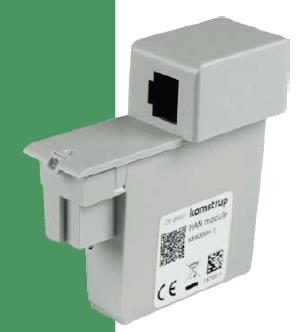 Kamstrup HAN-NVE module |
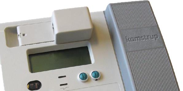 Kamstrup HAN-NVE module installed on the power meter |
¶ Procedure
If the HAN-NVE module is installed in the meter: Pull it out horizontally.
In some cases this may require using some force. There is no locking mechanism, the connector is just sometimes a tight fit.
Note: Do not bend or twist, pull it straight out.
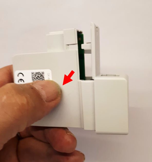
Remove the lid, which is released by pressing on each side of the box in the area indicated by red arrow below:
 |
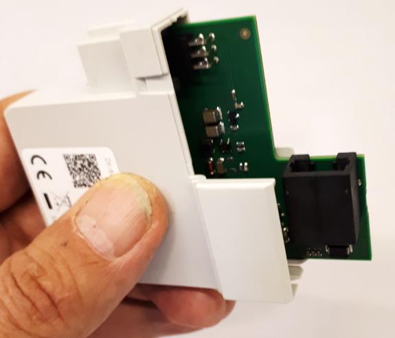 |
Remove the original board, place it in the protective bag the Pow-K was delivered in – and store it safely with the meter.
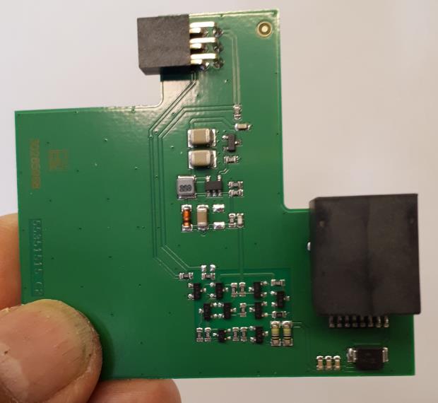
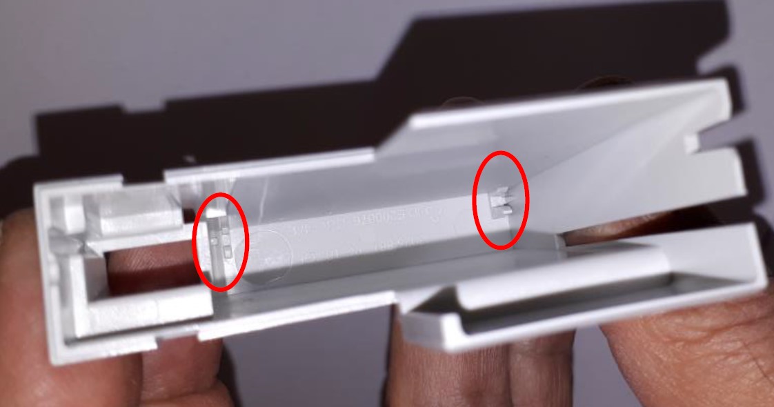
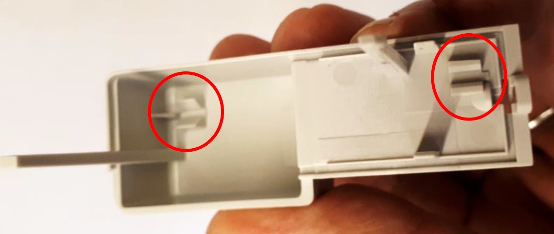
The card is held in position by four slots: Two in the bottom of the enclosure, two in the lid.
In the enclosure:
In the lid:
Position the Pow-K card in the slots of the lid, ensure it is correctly seated:
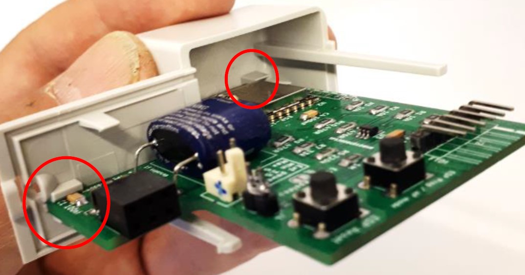
(Photo shows an early model of the Pow-K board)
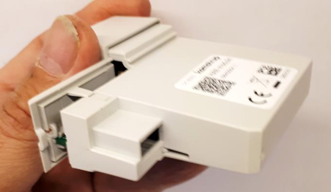
Place the enclosure over the board, pull lid and enclosure together until it snaps in place:
 |
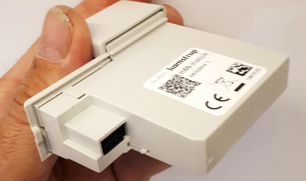 |
We recommend placing the original board of the HAN-NVE module in the ESD-protective bag the Pow-K is delivered in, and store it in the fuse cabinet close to the smart meter.
¶ Getting started
Once physically installed, follow the Getting started guide to connect the device to Wi-Fi and complete initial configuration. Pow-K specific configuration options are described below.
If your board is an older ESP8266 version (layout v1.4 or older), also check the board type setting — see the note in the Getting started guide.
¶ P1 configuration
Kamstrup Omnipower meters can be configured by the grid company to deliver data in 3 formats:
- HAN-NVE: Used in Norway, Sweden, Finland, Switzerland and Austria.
Serial data format: 2400 baud / 8N1 - DLMS push 1: Used in Denmark.
Serial data format: 2400 baud / 8N1 - HAN P1: Used in Sweden and Denmark (some late rollouts, since 2023)
Serial data format: 115 200 baud / 8N1
The Pow-K will autodetect bitrate and parity when it is started up the first time. If the autodetect for some reason fails, set the following in the configuration screen:
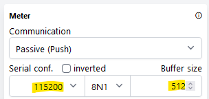
For more information on the types of payloads sent by the meter, see Omnipower(R) HAN Interface specification.
¶ Kamstrup 382M configuration
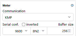
Boards with layout version v1.6.1 and newer can read Kamstrup 382M meters.
This is the configuration needed to read data from Kamstrup 382M:
¶ Optional (user installable) temperature sensor
Boards with layout version v1.6.1 and newer can accommodate a user-installed temperature sensor, type Dallas DS18B20. The necessary pullup resistor is installed.
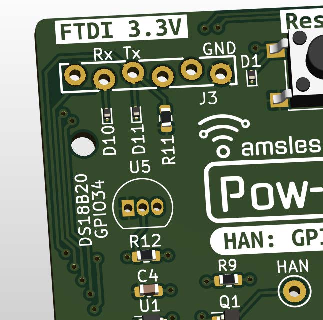
User installable temperature sensor DS18B20
Temperature sensor can be bought from mouser.com, digikey.com or other electronic component outlet.
¶ Installation
If you install the sensor component directly on the board, just drop it in and solder it.
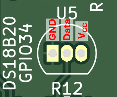
If you install a sensor with cable (such as the Shelly temperatursensor DS18B20 3m), observe the following pinout on the board:
¶ Activation
To activate the temperature sensor, user must change the hardware setting:
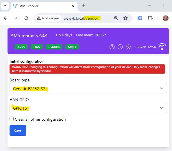
- Add "/vendor" to the URL and select "Generic ESP32-S2" and "GPIO16" from the dropdown lists:
- Click "Save"
- Open the Config page
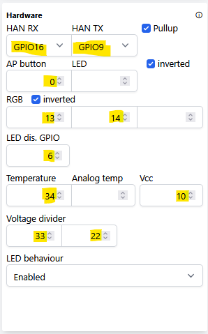
- You will now see an extended "Hardware" tile, with a field named "Temperature", which must be set to "34" (corresponding to "GPIO34" marked on the PCB).
Ensure the other settings shown here are correctly entered. Do not leave them blank, or the device could (worst case) become unresponsive - or some features may not work correctly.
- In the "User interface" tile, ensure that "Temperature plot" is set to "Auto" or "Enabled":
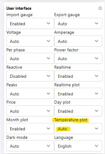
- Click the blue "Save" button (bottom right) to save the changes.
¶ 3D printing the holder
We provide two slightly different STL models, depending on printer technology.
¶ Resin (SLA) 3D printer
These printers have highest resolution, you can download a suitable STL file from this link.
¶ FDM 3D printing (using filament)
If you have good bed adhesion, the recommended method is to print the holder at a 45 degree angle. This minimizes the amount of support needed, and gives a nice and clean surface on the entire print. In your preferred slicer: Use “Support painting” and paint the end of the arm as indicated in the below illustration. Turn on “Automatic brim” to ensure the small surface on the build plate is well supported.
Download the STL file from this link.
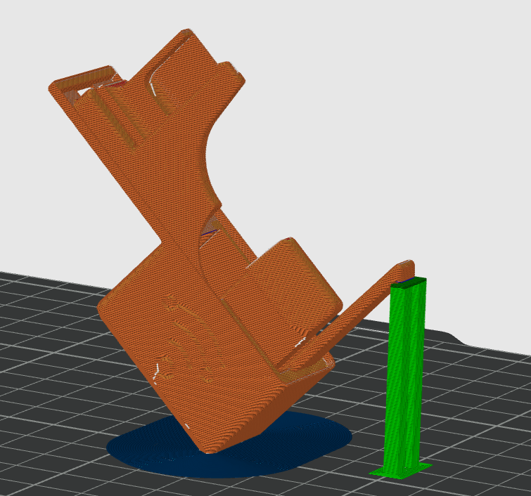
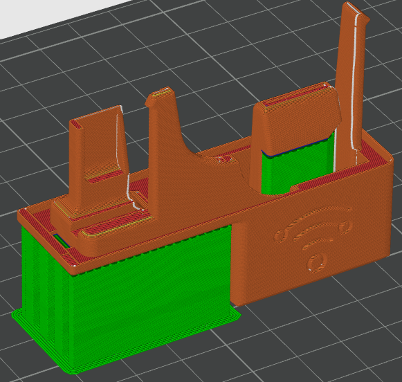
Should the angled print fail, or you are not confident on your bed adhesion, place it horizontally.
Support will be needed in two areas, marked dark blue below (use "Support painting").
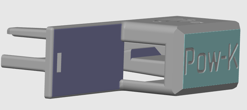
Slice it with your favorite support settings, it should look similar to this:
Happy printing!