¶ Technical specification
| Compatibility | Power meters with M-bus signal |
| Power meter interface |
|
| Connection | Wi-Fi 2.4GHz b/g/n |
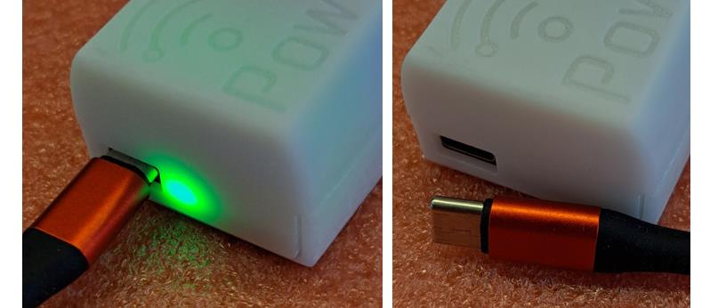
| Power | Powered from the meter during operations. Can be powered from USB while upgrading firmware manually. |
| Weight | 40 g |
| Size | 70 x 39 x 24 mm |
| Input voltage | M-bus up to 36V |
| Operating power | 0,5 W |
| Data encryption | Supported |
| MQTT | Internal and external, including SSL |
| Home Assistant auto discovery | Yes |
| Protection class | IP20 (suitable for use in dry conditions) |
| Temperature range | -20°C to +70°C |
| Humidity | Non-condensing |
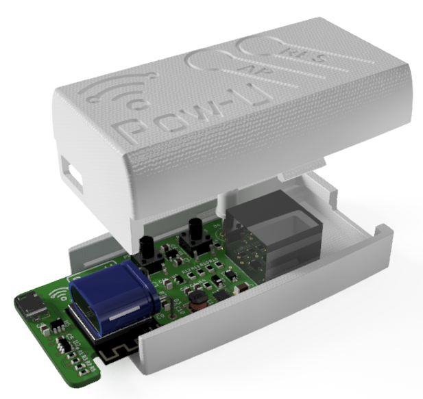
¶ Overview
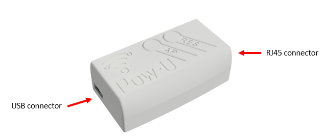
¶ For M-bus power meters with RJ12 or RJ45 socket
There are (as far as we know!) two different physical interfaces on power meters in Europe that deliver M-bus signal: RJ45 and RJ12.
¶ Nordic countries: Power meters with RJ45 socket
The M-bus signal is delivered on pins 1 and 2 of an RJ45 socket. The remaining 6 pins are not used.
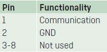
Base voltage is 24V, dropping to 12V when data bits are transmitted.
Used in Norway, Sweden and Finland(?), this interface is often referred to as HAN-NVE.
¶ Mid European countries: Power meters with RJ12 socket
The M-bus signal is delivered on pins 3 and 4 of an RJ12 socket. The remaining 4 pins are not used.
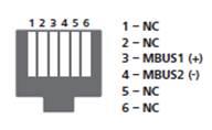
Base voltage is around 34V, dropping to 22V when data bits are transmitted.
Used in several Mid-European countries, this interface is often referred to as P1.
- Pow-U connects to a Nordic M-bus meters using an ordinary, straight RJ45 cable ("Ethernet cable"). Only one wire pair is used (pins 1 and 2).
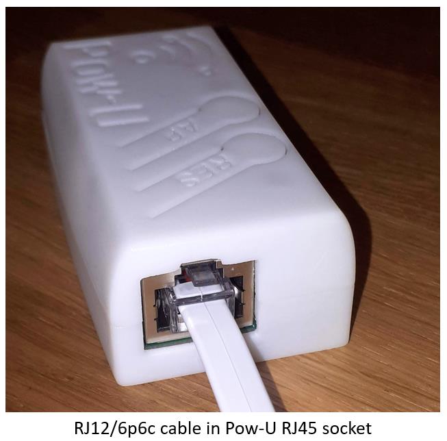
- Pow-U (layout v1.8.1 and newer) connects to Mid-European “P1” M-bus meters using a straight RJ12 cable ("Phone cable"). Only two wires are used (pins 3 and 4). The Pow-U has an RJ45 socket where an RJ12 connector can only enter in the correct centered position:
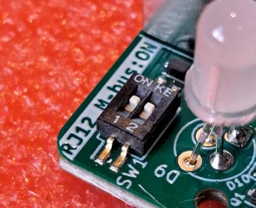
Pow-U boards have DIP switch selectors that must be set to ON position when used on Mid-European “P1” power meters:
¶ Encryption / Austria
Users in Austria with encrypted meters may encounter the following issue (we have specifically seen this with Netz Burgenland):
- The grid operator provides two encryption keys: Encryption key and Authorization key.
- When both keys are entered on the config page, a warning appears: HAN: Authentication failed
- If this occurs, delete the Authorization key from the config screen. (Do not delete the encryption key)
- The reader should now work as expected.
¶ Getting started
Once connected to the meter, follow the Getting started guide to connect the device to Wi-Fi and complete initial configuration.
¶ Buttons
There are two buttons:
- Pressing the RES / R button restarts the microcontroller. Restart is indicated by a blink sequence on the LED.
- Holding the AP / A button down for 5-10 seconds sets the device in Access point (AP) mode. Do this if you need to reconfigure the Wi-Fi setting.
Important: When in AP mode, the Pow-U must be powered from USB, as this mode consumes more current than the power meter can deliver.
AP mode is indicated by steady yellow light on the LED (on older firmware: short yellow blinks).
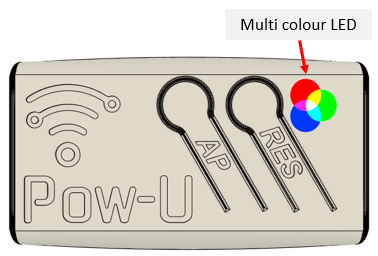
¶ Indicator LED
The multicolour LED gives the following indications:
- Steady yellow light when device is in Access point (AP) mode
- Rapid green/red/yellow blink sequence when restarting
- Blue blinking while data arrives from the power meter
- Short green blink immediately after blue blinking: Data is recognized as valid.
- Red blink codes indicates errors. See Firmware User Manual.
- Steady blue light when the device is powered but not connected to the power meter.
¶ Installing a temperature sensor on Pow-U
Unlike Pow-K and Pow-P1, the Pow-U does not have pads laid out for easy installation of a temperature sensor.
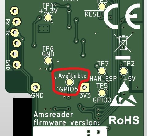
However, users can install a temperature sensor by exploiting the available GPIO5 that is exposed to a surface pad on the back side of the PCB. Pads delivering 3,3V and GND are also available:
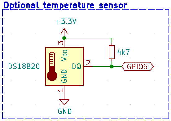
We recommend installing a digital temperature sensor, type Dallas DS18B20, as code supporting this sensor is included in the firmware.
A 4700 ohm resistor is also required.
The sensor should be installed like this:
To activate the temperature sensor, user must change the hardware setting:
- Add "/vendor" to the URL and select "Generic ESP32-S2" and "GPIO16" from the dropdown lists:
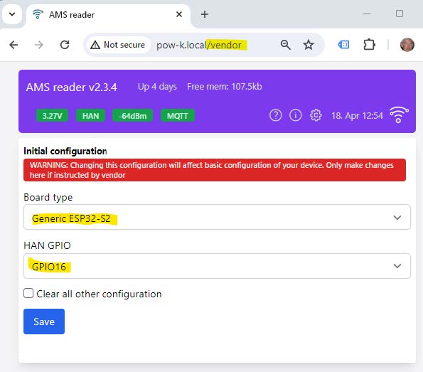
- Click "Save"
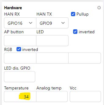
- Open the Config page
- You will now see a modified "Hardware" tile, with a field named "Temperature", which must be set to "5" (corresponding to "GPIO5" marked on the PCB):
(Note: The illustration below is not for Pow-U, the correct number is “5”.)
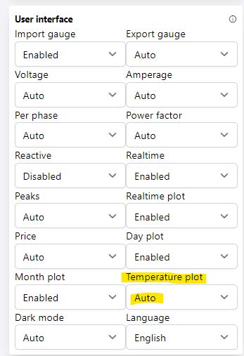
- In the "User interface" tile, ensure that "Temperature plot" is set to "Auto" or "Enabled":
- Click the blue "Save" button (bottom right) to save the changes.